The LED symbol is one of the most widely used symbols in electronic schematics. It represents a light-emitting diode and shows how the component should be connected within a circuit. Correct interpretation of the symbol is essential for identifying polarity, controlling current flow, selecting PCB footprints, and ensuring successful assembly.
In this guide, you will learn what the LED symbol means, how to identify the anode and cathode, how LED symbols differ from other diode symbols, how LEDs are used in circuit diagrams, and what engineers should consider during PCB design and manufacturing.
What Is an LED Symbol?
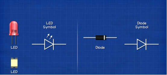
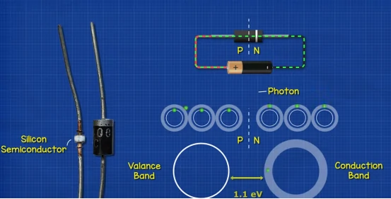
An LED symbol is the electronic symbol for a light-emitting diode. Engineers use it in schematic diagrams to show where an LED sits in a circuit. The symbol looks like a standard diode symbol with two arrows pointing outward.
The diode part shows one-way current flow. The outward arrows show light emission. This small visual difference makes the LED circuit symbol clearer than a normal diode symbol.
You will see LED symbols in power indicators, signal indicators, display modules, sensors, control panels, lighting boards, and embedded devices. When you read an LED in schematic form, check polarity, current path, and current control first.
LED Symbol Parts and Polarity
The LED symbol has two terminals. The anode is the positive side. The cathode is the negative side. Current flows from anode to cathode when the LED is forward biased.
The cathode side usually has a vertical bar in the schematic. This bar helps engineers identify the negative terminal quickly. If the LED is reversed, it may not light. In some circuits, excessive reverse voltage can damage the part.
| Feature | Anode | Cathode |
|---|---|---|
| Polarity | Positive | Negative |
| Current Direction | Current enters | Current exits |
| Schematic Clue | Opposite the bar | Bar side |
| Through-Hole Clue | Longer lead | Shorter lead or flat edge |
| PCB Marking | A or + | K or – |
SMD LED polarity can be less obvious than through-hole polarity. Some packages use a notch. Some use a green mark. Some use a chamfered corner. These marks vary by manufacturer, so engineers should always check the datasheet before PCB layout and assembly.
LED Symbol vs Diode Symbol
The LED symbol and diode symbol look similar, but they do not mean the same thing. A standard diode controls current direction. An LED controls current direction and emits light.
| Component | Symbol Difference | Main Function |
|---|---|---|
| LED | Diode symbol with outward arrows | Emits light |
| Standard Diode | No light arrows | Controls current direction |
| Photodiode | Arrows point inward | Detects light |
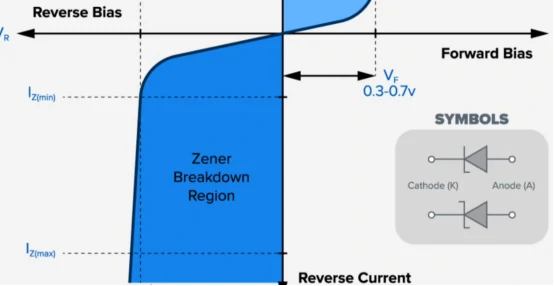
| Zener Diode | Bent cathode line | Regulates voltage |
| Laser Diode | LED-like symbol | Produces focused light |
Common LED symbol variations include infrared LED, UV LED, bi-color LED, RGB LED, high-power LED, SMD LED, and addressable LED symbols such as WS2812B or SK6812. More complex LEDs may need extra pins for power, ground, data input, and data output.
LED Symbol in Circuit Diagrams
The LED symbol becomes more useful inside a real circuit. A symbol shows component identity. A circuit diagram shows behavior.
Simple LED and Resistor Circuit
A basic LED circuit uses one LED and one resistor. The resistor limits current. The LED emits light. This design is simple, low-cost, and reliable for indicators.
Most LEDs should not connect directly to a voltage source. Direct connection can create excessive current and shorten LED life. A resistor or driver protects the LED and controls brightness.
LED Indicator Circuit
LED indicator circuits provide visual feedback for power, charging, communication, alarm, and fault conditions. Compared with display screens, LED indicators are smaller, cheaper, and easier to read from a distance.
Series and Parallel LED Circuits
A series LED circuit places multiple LEDs in one current path. This design gives better current matching but needs a higher supply voltage.
A parallel LED circuit places LEDs in separate branches. This design gives more layout flexibility but needs better current control. Each branch should usually have its own resistor or driver path.
LED Driver Circuit
A driver circuit controls LED current more accurately than a simple resistor. High-power LEDs, lighting boards, automotive lamps, and industrial indicators often need constant-current drivers. Better current control creates more stable brightness and higher reliability.
LED Electrical Values Engineers Should Know
The LED symbol shows function, but the datasheet shows electrical limits. Engineers should check forward voltage, forward current, reverse voltage, power rating, and thermal conditions before finalizing the circuit.
LED Forward Voltage
Forward voltage is the voltage drop across the LED during normal operation. Different LED colors usually have different forward voltage values. Red LEDs often need less voltage than blue or white LEDs.
| LED Color | Typical Forward Voltage | Common Use |
|---|---|---|
| Red | 1.8–2.2V | Power indicators |
| Yellow | 2.0–2.2V | Status indicators |
| Green | 2.0–3.2V | Operation signals |
| Blue | 3.0–3.4V | Modern electronics |
| White | 3.0–3.5V | Lighting and backlight |
LED Resistor Calculation
You can calculate a basic current-limiting resistor with this formula:
R = (Vsupply − Vf) / I
Vsupply is the supply voltage. Vf is the LED forward voltage. I is the target LED current. For example, a 5V circuit uses a red LED with a 2V forward voltage. If the target current is 10mA, the resistor value is 300 ohms. A slightly higher standard value can reduce current and improve safety margin.
From LED Symbol to PCB Footprint
A schematic symbol is not enough for manufacturing. Engineers must connect the LED symbol to the correct PCB footprint. This step links the logical circuit to the physical board.
LED symbol → component library → PCB footprint → PCB layout → assembly → testing
A good PCB layout design process checks symbol pins, footprint pads, datasheet polarity, and package dimensions before production. This review is especially important for SMD LEDs because package markings are not always consistent.
Common LED PCB Footprints
Common packages include 0402, 0603, 0805, 1206, 3528, 5050, and high-power LED footprints. Small packages save board space. Larger packages improve visibility and assembly handling. High-power packages need stronger thermal design.
Pin Mapping Verification
Pin mapping errors can make a correct schematic fail on the real board. The schematic may show the right polarity, but the footprint may reverse anode and cathode pads. Engineers should compare the datasheet, symbol, footprint, and 3D model before releasing Gerber files.
PCB Assembly Considerations for LEDs
PCB assembly makes the schematic real. A correct LED symbol still needs clear manufacturing data. The BOM, CPL file, silkscreen, and assembly drawing should all support the same LED orientation.
Polarity Marking and Rotation Data
Clear silkscreen marking helps assembly teams place LEDs faster and more accurately. Engineers can mark polarity with +/-, A/K, or a diode outline. The “K” mark usually means cathode.
SMT assembly also needs correct pick-and-place rotation data. If the rotation is wrong, the LED can be placed backward even when the schematic is correct. Professional PCB assembly services check component orientation, polarity marks, and first-article samples before volume production.
AOI Inspection
Automated optical inspection can detect many LED placement issues. AOI systems compare the assembled board against expected images and placement rules. This process is faster than manual inspection and more consistent for repeated production.
LED Testing Before Production
LED circuits should be tested before mass production. Engineers should confirm light output, polarity, current, thermal behavior, and visual consistency. A small prototype test can prevent a large batch failure.
For indicator LEDs, engineers should check brightness under normal operating voltage. For RGB or addressable LEDs, they should test color order, data direction, and software control. For lighting boards, they should check heat rise, driver performance, and long-term stability.
LED Design Checklist for Engineers
Before releasing an LED PCB design, engineers should verify these items:
- Confirm anode and cathode in the schematic.
- Match the symbol pins with the PCB footprint.
- Check LED forward voltage and target current.
- Add a resistor or constant-current driver.
- Review silkscreen polarity marks.
- Verify pick-and-place rotation data.
- Check thermal design for high-power LEDs.
- Test the first sample before volume production.
This checklist is simple, but it removes many common LED design and assembly mistakes.
Conclusion
The LED symbol may look simple, but it carries important design information. It identifies the light-emitting diode, shows polarity, and helps engineers understand current direction in a circuit.
A better LED design process goes beyond drawing the symbol. Engineers should verify the datasheet, match the symbol to the footprint, mark polarity clearly, check assembly files, and test the first article before production. These steps make the final PCB more reliable and reduce costly rework.
At Fast PCB Layout, we help engineessrs turn schematic designs into reliable printed circuit boards through PCB fabrication, PCB assembly, prototyping, and DFM review.
Instant quotes for PCBA solutions: https://fastpcblayout.com/contact-us/
FAQs
What happens if an LED is connected backward?
Most LEDs will not light when connected backward. If the reverse voltage is too high, the LED may be permanently damaged.
Can an LED work with AC power?
Yes, but most LEDs need extra circuitry such as a rectifier, resistor, capacitor, or LED driver to operate safely with AC power.
Which LED package is common for PCB assembly?
0603, 0805, and 1206 are common SMD LED packages. They balance visibility, assembly efficiency, and board space.
Why should engineers test LED circuits before mass production?
Testing helps confirm polarity, brightness, current, color, thermal behavior, and assembly accuracy before a large production batch starts.