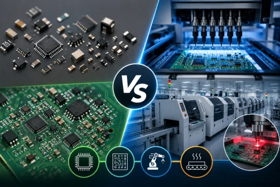
SMD vs SMT is a common question in PCB design and electronics manufacturing. Many engineers, buyers, and product developers use these two terms together. However, they do not mean the same thing.
SMD stands for Surface Mount Device. It means the electronic component. SMT stands for Surface Mount Technology. It means the assembly process that mounts SMD components onto a printed circuit board.
If you design, source, or build electronic products, this difference matters. It affects PCB layout, component selection, assembly cost, solder quality, inspection, and long-term reliability. At Fast PCB Layout, we help customers connect PCB design, fabrication, and assembly decisions before PCBA production starts.
SMD vs SMT: Key Differences
The main difference between SMD vs SMT is function. SMD describes the part. SMT describes the manufacturing method.
An SMD can be a resistor, capacitor, LED, sensor, microcontroller, QFN, BGA, or IC package. SMT is the process that places these parts onto PCB pads and solders them in position.
Engineers choose SMD components during circuit design. PCB manufacturers use SMT during assembly. Both choices affect board size, production cost, yield, and reliability.
| Category | SMD | SMT |
|---|---|---|
| Full Form | Surface Mount Device | Surface Mount Technology |
| Meaning | Electronic component | PCB assembly method |
| Main Role | Performs electrical functions | Mounts components onto PCB pads |
| Examples | SMD resistor, SMD LED, QFN, BGA | Solder paste printing, pick-and-place, reflow |
| Main User | PCB designers and hardware engineers | PCB assemblers and manufacturers |
| Quality Focus | Package quality and component reliability | Solder joint quality and process yield |
As a Fast PCB Board Manufacturer, we often see one practical issue. A good SMD choice can still fail if the SMT process is weak. A strong design and a stable assembly process must work together.
What Is SMT?
What is SMT? SMT means Surface Mount Technology. The SMT full form is Surface Mount Technology. To define SMT clearly, SMT is a PCB assembly process that mounts electronic components directly onto the surface of a printed circuit board.
SMT is faster, smaller, and more automated than traditional through-hole assembly. It helps manufacturers build compact products with higher component density and lower production costs.
Good SMT assembly starts before production. A strong PCB layout design helps reduce solder bridging, tombstoning, poor alignment, and signal problems. Better design creates smoother assembly and higher yield.
Where Is SMT Used?
SMT is widely used in consumer electronics, automotive electronics, medical devices, IoT products, robotics systems, LED lighting products, industrial controllers, aerospace electronics, and telecom equipment.
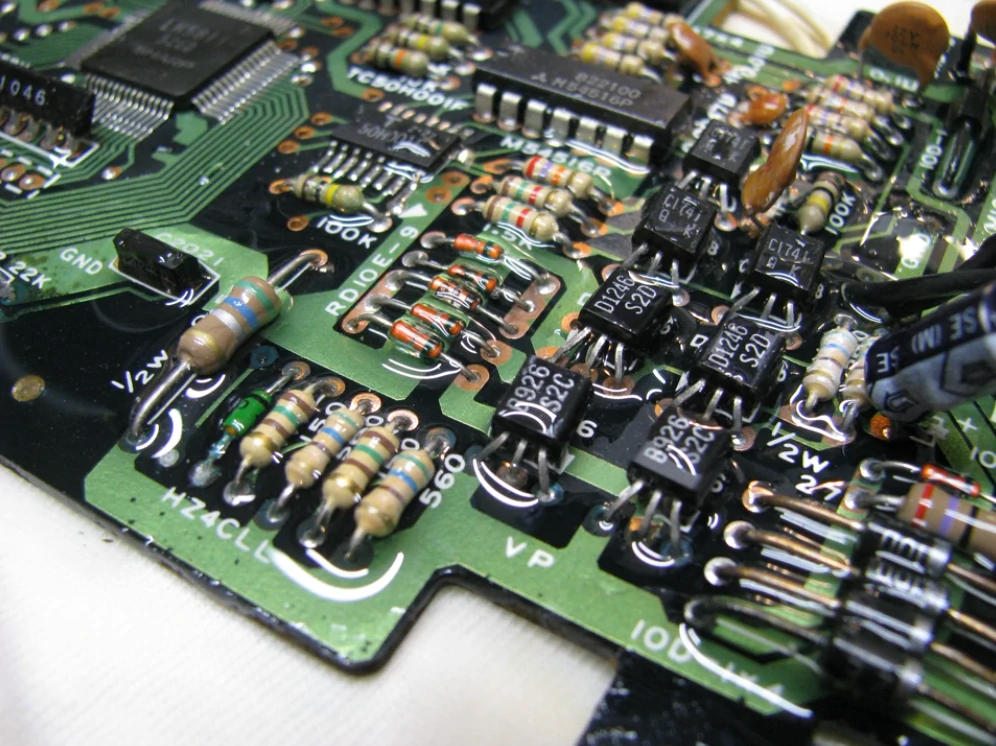
What Is a SMD?
What is a SMD? A Surface Mount Device is an electronic component designed for SMT assembly. It mounts directly onto PCB pads instead of passing through drilled holes.
The term SMDs meaning refers to multiple Surface Mount Devices. A modern smd printed circuit board can contain hundreds or thousands of SMDs.
Common SMD Components
Passive SMD components include resistors, capacitors, inductors, and ferrite beads. These parts control current, store energy, filter noise, and stabilize circuits.
Active SMD components include microcontrollers, memory chips, sensors, MOSFETs, power ICs, and communication modules. These devices process signals and control electronic functions.
Common SMD Package Types
| SMD Package | Common Use | Design Note |
|---|---|---|
| 0201 / 0402 / 0603 | Resistors and capacitors | Good for compact electronics |
| SOIC | Analog ICs and drivers | Easier to inspect and rework |
| QFP | Microcontrollers | Visible leads support inspection |
| QFN | RF and power ICs | Needs accurate solder paste control |
| BGA | Processors, FPGAs, memory | Requires X-ray inspection |
Smaller SMD packages save board space. Larger packages are easier to inspect and rework. Engineers should choose packages based on product size, thermal load, signal speed, and assembly capability.
How SMT Assembly Works
SMT assembly turns a bare PCB into a working PCBA. The process connects SMD components to PCB pads through controlled soldering and inspection.
Step 1: PCB Fabrication
The process starts with the PCB fabrication process. The manufacturer creates copper traces, solder mask, vias, surface finish, and assembly pads. A reliable board improves SMT results.
Step 2: Solder Paste Printing
The manufacturer applies solder paste through a stencil. Paste volume must be accurate. Too much paste can cause bridging. Too little paste can create weak solder joints.
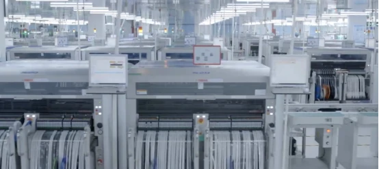
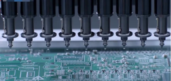
Step 3: Pick-and-Place Assembly
A pick-and-place machine places SMD components onto the pasted pads. This process is faster and more repeatable than manual placement.
Step 4: SMD SMT Soldering
SMD SMT soldering usually uses reflow soldering. The PCB moves through a reflow oven. Heat melts the solder paste and forms permanent electrical connections.
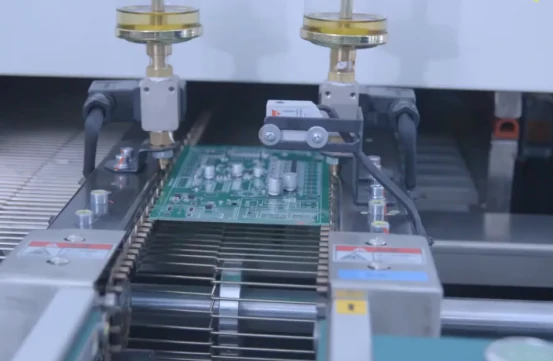
Step 5: Inspection and Testing
Manufacturers use SPI, AOI, X-ray inspection, functional testing, and in-circuit testing to verify quality. X-ray inspection is especially important for BGA and hidden solder joints.
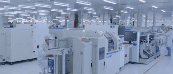
Professional PCB assembly services combine process control, inspection equipment, and engineering review to improve yield and reduce rework.
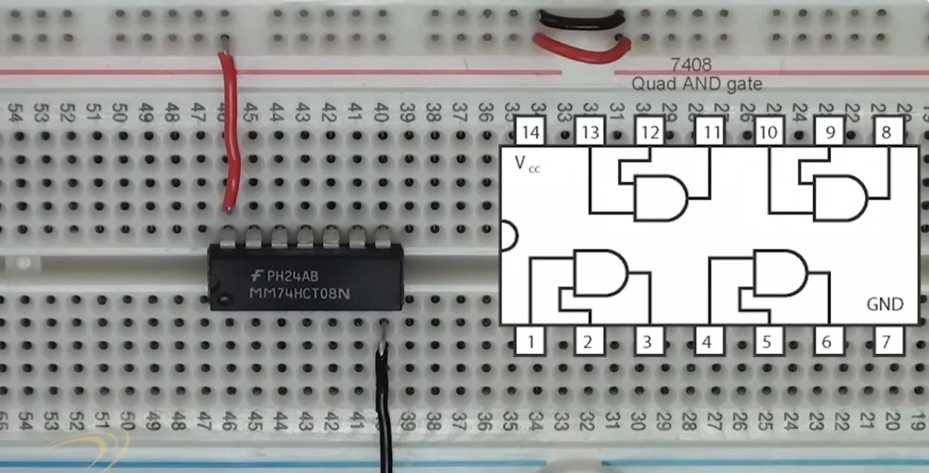
SMT vs Through-Hole Technology
SMT and Through-Hole Technology both have value. SMT is better for compact, automated, and high-volume products. Through-hole technology is better for parts that need stronger mechanical support.
| Factor | SMT | Through-Hole Technology |
|---|---|---|
| Board Density | Higher | Lower |
| Assembly Speed | Faster | Slower |
| Automation | Excellent | Limited |
| Mechanical Strength | Moderate | Higher |
| Repair Difficulty | Higher | Lower |
| Best Use | Compact electronics | Connectors and high-stress parts |
When SMT Is Better
SMT is better for IoT devices, consumer electronics, automotive modules, medical devices, telecom products, robotics boards, and industrial controllers. These products need smaller size, higher density, and consistent production.
When Through-Hole Is Better
Through-hole is better for heavy connectors, transformers, relays, large capacitors, power terminals, and parts exposed to repeated mechanical stress.
Hybrid Assembly
Many boards use both technologies. This is called hybrid assembly. A smart controller may use SMT chips and through-hole terminal blocks on the same board.
Why SMT Dominates Modern Electronics
SMT dominates modern electronics because products need smaller size, faster production, higher density, and more consistent quality.
Higher Component Density
SMT places components directly on the PCB surface. This allows engineers to use both sides of the board. The result is denser and more compact than traditional assembly.
Lower Manufacturing Costs
SMT reduces manual labor. Automated machines place components faster and more consistently than manual workers. This lowers unit cost when production volume increases.
Better High-Speed Performance
SMD components use shorter electrical paths. Shorter paths can reduce parasitic inductance and capacitance. This helps high-speed circuits perform better.
Broader Industry Fit
Consumer electronics use SMT because products need compact layouts. Automotive electronics use SMT because control modules need stable production and repeatable quality. Medical devices use SMT because designs often need small size and reliable performance. Industrial automation products use SMT because manufacturers need scalable assembly.
SMD PCB Design Considerations

An SMD PCB must support accurate placement, strong solder joints, clean inspection, and long-term reliability. PCB design affects assembly quality more than many buyers expect.
Design for Manufacturability
Engineers should control pad dimensions, solder mask clearance, component spacing, fiducial marks, and panelization. These details help machines place parts accurately.
Design for Assembly
A simpler assembly is faster to build. Clear component orientation, proper spacing, and accessible inspection areas reduce production problems.
Signal Integrity
SMT supports shorter electrical paths than through-hole technology. Shorter paths help high-speed signals travel with less distortion.
Thermal Management
Power devices generate heat. Engineers should use thermal vias, copper pours, and heat-spreading structures to improve temperature control.
Design for Testing
Test points, programming headers, and inspection access help manufacturers validate the finished PCBA more efficiently.
How to Choose an SMT Assembly Partner
A good SMT assembly partner does more than place components. It helps engineers find design risks before production. It also controls quality during fabrication, assembly, inspection, and testing.
Check Manufacturing Capability
You should check whether the supplier can support prototypes, low-volume builds, mass production, fine-pitch parts, QFN packages, and BGA assembly.
Check Inspection Capability
You should look for SPI, AOI, X-ray inspection, and functional testing. Better inspection creates better process control.
Check Engineering Support
A strong supplier can review Gerber files, BOM files, pick-and-place files, panelization, and DFM risks before production starts.
Check Quality Standards
Buyers should ask about IPC-A-610, IPC J-STD-001, traceability, component control, and final inspection records.
Many OEMs prefer complete electronics manufacturing services because one supplier can manage PCB fabrication, component sourcing, SMT assembly, testing, and delivery. This reduces communication cost and shortens project time.
Conclusion
SMD vs SMT is easy to understand when you separate the component from the process. SMD is the surface-mount component. SMT is the technology that mounts and solders that component onto a PCB.
Modern electronics continue to move toward smaller SMD packages, denser PCB layouts, faster SMT automation, and more advanced inspection systems. Engineers who understand these details can design better products and avoid costly assembly problems.
If you need prototype PCBA, turnkey assembly, or production support, Fast PCB Manufacturing Company can help you evaluate your design and request instant quotes for PCBA solutions.
FAQs
Is every SMD assembled using SMT?
Most SMD components are assembled using SMT processes such as solder paste printing, pick-and-place assembly, and reflow soldering. Some repairs or prototypes may use manual soldering.
Can SMT assembly be done manually?
Yes, simple SMT assembly can be done manually for repair or prototypes. However, automated SMT assembly is faster, more accurate, and more reliable for production.
What is the difference between SMA, SMD, and SMT?
SMD means Surface Mount Device. SMT means Surface Mount Technology. SMA means Surface Mount Assembly, which usually refers to the finished assembly result after SMT processing.
Why are SMD components smaller than through-hole components?
SMD components are smaller because they do not need long leads that pass through drilled holes. Their compact terminals attach directly to PCB pads.
What files should I send for SMT PCB assembly?
You should send Gerber files, BOM files, pick-and-place files, assembly drawings, testing requirements, quantity, lead time target, and any special quality requirements.