Ground and Power planes are large copper areas on the PCB that are engineered, designed, and placed to provide a stable return path for electrical current. This placement helps to reduce noise, improve signal quality, and help cool the board by spreading heat.
A ground plane provides a common reference point and return path for the signal, it also works as a heat dissipator for the components. The power plane, on the other hand, provides power for every component and distributes power throughout the PCB. There are various benefits of a power plane, but the power plane needs to be designed carefully, otherwise, it can cause interference, especially if used for a mixed signal design.
In short, you can say that a proper ground and power plane is required for a safe and reliable electronic design, especially when working with high-power and high-density boards where noise and interference are risk factors. There are many techniques like dedicated ground planes, ground vias, and galvanic isolation that help manage these issues, and in this article, we will talk about those and many other things.
Different Types of Ground Planes in a Circuit Board
From the intro section, you know that the ground plane is one of the most important parts of any PCB design, but if you are a beginner on PCB design, you will face a lot of problems understanding the schematic because there are different types of ground planes, each with its own symbol in the schematic.
Different symbols help PCB designers to place the ground plane in a way that it reduces noise and ensures reliability. In this section, we will learn about the different types of grounds and their terminology.
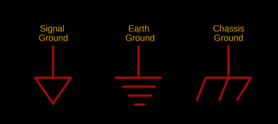
Signal Ground
Signal ground is the common return path for all low-power signals in a PCB. It’s a point where the voltage of different signals can be measured. Signal ground is there to maintain a constant reference for the sensitive electronics in your PCB.
Chassis Ground
The chassis ground connects the PCB or internal circuits to the metal body (chassis) of a device. It helps shield the system from electrical noise and provides a common reference point inside the device. The chassis ground may or may not be connected to Earth’s ground.
Earth Ground
Earth ground is a physical connection to the earth (ground) itself, like through a grounding rod or a ground port in the outlet. It protects from electric shock by providing a safe path for fault currents to flow into the earth.
Power Ground
Power ground is used for high-current circuit parts like power supplies and motors. It keeps heavy current paths away from sensitive signal areas to prevent interference.
Analog and Digital Ground
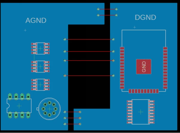
Analog ground is used for components that work with continuous, smooth voltage or current levels. It keeps the noise low to ensure accurate readings. Components that use analog ground are sensors, ADCs (Analog-to-Digital Converters), DACs (Digital-to-Analog Converters), and amplifiers.
Digital ground is used for components that work with fast, on-off (binary) signals. It helps manage the high-frequency noise created by rapid switching. Components that use digital ground are microcontrollers, FPGAs, memory chips, and logic gates.
There is a great paper on Grounding in mixed-signal systems demystified from Texas Instruments, you can check that out if you want to know more about the topic. And I will recommend you to read through this paper once, cause there will be ground loop issues with analog and digital ground when you want to route traces for the PVB.
Virtual and Floating Ground
Aside from the above-mentioned ground concepts, you may sometimes hear about Virtual ground and floating ground. These are not related to PCB design, but since we’re talking about grounding, I feel like explaining everything in one place.
Virtual Ground
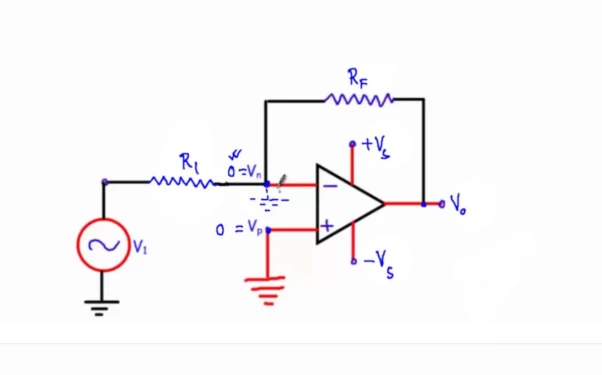
A virtual ground is not a real ground but can be treated like one for analysis. In op-amp circuits, especially in inverting amplifiers, the node at the inverting input is held at nearly 0V without a physical ground connection. Thanks to the op-amp’s high gain and negative feedback, this simplifies calculations by allowing us to assume the voltage at that point is zero, making circuit analysis much easier. In the above image, Vn is the virtual ground.
Floating Ground
In an isolated system, a floating ground is a reference point that is not directly connected to the earth. Because of this, the voltage at the ground terminal remains uncertain or floating. This behavior of any electric circuit can cause a problem, but sometimes it’s intentionally done for safety reasons. For a more detailed explanation, you can check out spellmanhv’s article on floating ground.
Best Practices for Power Planes and Ground Planes in PCBs
Layer Stack-Up
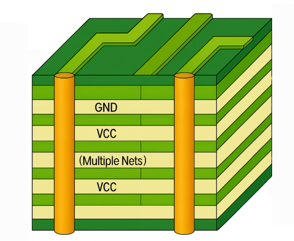
A PCB is made by sandwiching layers of copper and insulating material one after another — this is called a layer stack-up. In a multi-layer PCB, this stack-up becomes more complex, so what I recommend i a balanced layer stack-up. This not only reduces noise and EMI, it also adds to mechanical strength, and you get less warping while soldering. If you are working on a mixed signal board, then placing the power and ground planes next to each other reduces EMI. In four-layer or more boards, even stack-ups with power planes are the best.
Ground Planes for Dual-Layer Boards
If you are working on a single-layer or double-layer board, you may want to skip the power plane, and it’s advised that you only add a ground plane and route the power manually with a thick trace. This reduces complexity and improves EMI.
Power Plane Size
For a more complex multi-layer PCB, extending the power plane across the entire PCB area and making a separate plane for power reduces the impedance and minimizes voltage drop.
Ground Loops
Ground loops happen when there are multiple return paths because of different ground voltages across the board. This is mostly not a concern if you are working with digital electronics, but it’s a problem if you are working with analog or high-frequency design.
To avoid a ground loop, connect each component to the ground plane either by a via or use a very short trace to route the ground to the ground plane. If you don’t have a ground plane, use small traces (6–8 mil for signals, 15–25 mil for power and ground), but remember that trace width depends on how much current it carries.
Via Stitching
Use multiple vias between power planes and pads to lower inductance. Add via stitching along power plane edges to improve shielding and reduce EMI.
Decoupling Capacitors
To reduce noise and EMI-related related, you can just place a decoupling capacitor close to the IC power pins. Use different capacitor values connected in parallel to filter various frequencies. As a rule of thumb, you can use 103, 104, and 105 pF in parallel near a power pin.
Domain Splitting
Split power planes into domains for different voltage needs. Follow EMI/EMC rules to prevent noise and crosstalk. For better efficiency, use separate power rails for each circuit instead of a shared plane.
Power Plane Splitting
When components need different voltages, split the power plane into separate areas.
However, splitting can cause more EMI/EMC issues, so it’s safer to fully separate analog, digital, and high-power circuits. Sometimes it’s better to skip power planes and use separate power rails while keeping a solid ground plane for noise control.
Conclusion
A good grounding in a PCB is very important if you want your electronics to work well and stay reliable. Using techniques like ground planes, vias, and careful layout can help reduce noise and keep everything running smoothly. Knowing the different types of grounds and how to use them right also helps with heat, interference, and overall performance. No matter what kind of board you’re making, paying attention to grounding will save you a lot of trouble and make your design way better.
Supply planes help reduce noise and keep signals clear, but they can also cause issues, especially in mixed-signal designs. Designers need to plan the return current paths carefully to avoid interference with nearby components. One way to solve this is by optimizing the layer stack-up, which arranges layers in a way that keeps return currents short and efficient. Adding decoupling capacitors also helps with noise control.
In mixed-signal designs, it’s best to separate analog and digital components as much as possible to avoid signal problems. If separate ground planes are needed for safety reasons, it’s okay, but in most cases, using a single ground plane with techniques like net ties or safety capacitors works well. Via fences can also help reduce noise in these designs.