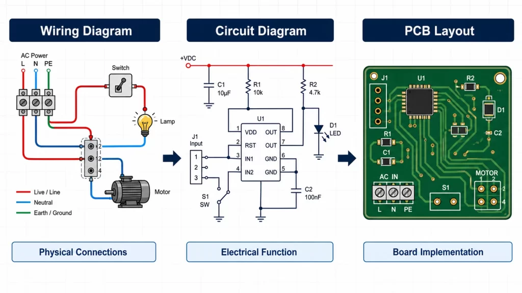
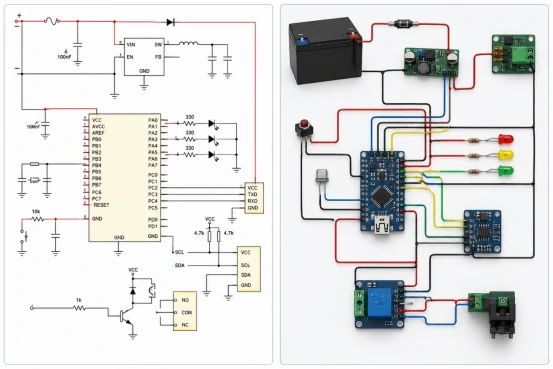
A wiring diagram shows how real wires, terminals, connectors, and devices are connected. A circuit diagram, also called a schematic diagram or electrical schematic, shows how components work electrically. For PCB layout, the schematic is usually the required file, while the wiring diagram supports installation and off-board connections.
The wrong drawing can slow review, assembly, repair, and manufacturing. A house wiring diagram, lighting wiring diagram, or wiring harness diagram answers a different question from a circuit schematic used for electronics design.
Table of Contents
- Wiring Diagram vs Circuit Diagram: What Is the Difference?
- What Is a Wiring Diagram?
- What Is a Circuit Diagram or Electrical Schematic?
- Wiring Diagram vs Schematic: Are They the Same?
- Types of Wiring Diagrams and Electrical Diagrams
- How to Read a Wiring Diagram or Circuit Diagram
- Circuit Diagram vs PCB Layout
- Which Diagram Should You Send for PCB Design or Assembly?
- Conclusion
- FAQ
Wiring Diagram vs Circuit Diagram: What Is the Difference?
The key difference is purpose. A wiring diagram shows physical connection. A circuit diagram shows electrical function. If a technician needs to connect a wire to a terminal, a wiring diagram is the better drawing. If an engineer needs to review voltage rails, signal paths, or component values, a circuit diagram is the better drawing.
For a relay cabinet, the wiring diagram helps prevent wrong terminal connections. For a sensor board, the circuit schematic shows pull-up resistors, protection diodes, regulators, and MCU pins. If a PCB layout is made from only a wire diagram, important electrical details may be missing.
| Item | Wiring Diagram | Circuit Diagram / Schematic |
|---|---|---|
| Main purpose | Shows real wires, terminals, connectors, and cable paths. | Shows components, values, power rails, nets, and signal flow. |
| Common use | House wiring, room wiring, lighting wiring, harness assembly. | Electronics design, circuit analysis, PCB layout, troubleshooting. |
| Typical user | Electrician, installer, service technician, cable assembler. | Electronics engineer, PCB designer, test engineer. |
| Enough for PCB design? | Usually no. | Yes, if values, pinouts, and designators are complete. |
What Is a Wiring Diagram?

A wiring diagram is an electrical connection diagram for physical hardware. It shows how wires connect to switches, lamps, motors, sensors, relays, plugs, sockets, terminal blocks, or control panels. A simple wiring diagram may only show one lamp and one switch. A complex wiring diagram may show a full machine cabinet or wire harness.
<p>In house wiring diagrams, the drawing may show live, neutral, ground, outlets, lights, and wall switches. In industrial wiring diagrams, it may show terminal numbers, wire colors, cable tags, fuse positions, and safety relays. If the main risk is a wrong physical connection, a wiring diagram is easier to use than a schematic circuit diagram.</p>
A wiring diagram also helps when a PCB connects to off-board hardware. For example, PCB assembly may need a separate connection diagram for front-panel switches, battery packs, fans, sensors, or external LED modules.
What Is a Circuit Diagram or Electrical Schematic?
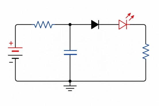
A circuit diagram shows how an electrical or electronic circuit works. It uses schematic symbols for resistors, capacitors, diodes, transistors, ICs, connectors, power rails, and ground. The drawing does not need to match the real position of parts on the board.
A circuit schematic is used to review function. It shows whether a signal has the right pull-up resistor, whether an input has protection, and whether a power rail has enough filtering. For electronic hardware design, the schematic also links reference designators such as R1, C3, U2, and J1 to the BOM and PCB layout.
Lorem ipsum dolor sit amet, consectetur adipiscing elit. Ut elit tellus, luctus nec ullamcorper mattis, pulvinar dapibus leo.
If a connector pin is wrong in the schematic, the final PCB can be wrong even when the board drawing looks clean. That is why a circuit diagram is not just a picture. It is the electrical source file for design review, layout, testing, and manufacturing.

Wiring Diagram vs Schematic: Are They the Same?
A wiring diagram and a schematic are not the same, although people sometimes use the terms loosely. A wiring schematic may show simplified connections, but a true electrical schematic must show how the circuit works. A wire diagram may show that two devices connect, but it may not show resistor values, IC pin functions, or protection circuits.
For a lighting circuit diagram, a wiring view may be enough to install a switch and lamp. For an LED driver circuit, the schematic must show the inductor, MOSFET, diode, current sense resistor, capacitor values, and feedback network. The same word “diagram” can describe very different engineering documents.
A practical rule is simple: use a wiring diagram for physical installation and service; use a schematic diagram for electrical design and PCB work.
Reference Designators in Circuit Diagrams
| Component Type | Common Designator | Example |
|---|---|---|
| Resistor | R | R1, R2 |
| Capacitor | C | C1, C2 |
| Inductor | L | L1, L2 |
| Transistor | Q | Q1, Q2 |
| Integrated Circuit | U | U1, U2 |
| Connector | J | J1, J2 |
Types of Wiring Diagrams and Electrical Diagrams
The common types of wiring diagrams include simple wiring diagrams, house wiring diagrams, room wiring diagrams, lighting wiring diagrams, wall wiring diagrams, and wiring harness diagrams. Each type focuses on physical connection, not detailed circuit behavior.
Electrical diagrams can include schematic diagrams, block diagrams, single-line diagrams, pictorial diagrams, ladder diagrams, pinout diagrams, and PCB layouts. If a project involves power distribution, a single-line diagram may be enough for early review. If it involves electronics, the circuit schematic and PCB layout are more important.
| Diagram Type | Best Use | Limitation |
|---|---|---|
| Wiring diagram | Install wires, cables, terminals, switches, and field devices. | Does not fully explain circuit function. |
| Schematic diagram | Design and debug electronic circuits. | Does not show real cable routing. |
| Block diagram | Show system modules and high-level signal flow. | Too simple for layout or assembly. |
| Pinout diagram | Show connector pins and signal names. | Cannot replace a full schematic. |
| PCB layout | Show copper traces, pads, vias, and component placement. | Hard to read without the schematic. |
How to Read a Wiring Diagram or Circuit Diagram
To read a wiring diagram, start from the power source and follow each wire to the load and return path. Check labels before wire colors because cable suppliers and old repairs may change colors. For a home electrical diagram, identify the breaker, switch, light, outlet, neutral, and ground before checking branches.
To read a circuit diagram, start with power input and ground. Then read each function block: protection, regulation, control, input, output, and connector. A good electrical schematic should include reference designators, values, net names, and clear connector pins.
If a drawing has no values, no pin numbers, and no reference designators, it is closer to a sketch than a production-ready circuit drawing. That kind of drawing may help discussion, but it should not be used directly for PCB manufacturing.
Circuit Diagram vs PCB Layout
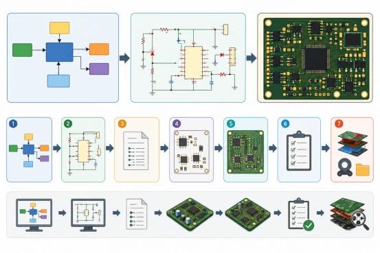
A circuit diagram defines what must connect electrically. A PCB layout defines how that circuit becomes copper, pads, vias, footprints, and component placement. The schematic creates the netlist, while the PCB layout turns the netlist into a manufacturable board.
For PCB projects, schematic vs layout is a critical difference. The schematic may show a decoupling capacitor beside an IC symbol, but the PCB layout decides whether that capacitor is physically close enough to work well. If a high-speed signal, power path, or thermal area is placed poorly, the board can fail even when the circuit diagram is correct.
For old or unclear products, PCB reverse engineering may be needed to rebuild both the schematic and layout data before redesign or production.
Which Diagram Should You Send for PCB Design or Assembly?
For PCB layout, send the schematic diagram, component datasheets, board outline, connector pinout, mechanical limits, and special routing notes. A wiring diagram can be included if the PCB connects to cables, switches, motors, batteries, or sensors.
For PCB manufacturing and assembly, send Gerber files, drill files, BOM, pick-and-place file, assembly drawing, polarity notes, and test requirements. If a supplier receives only a wiring diagram, they may need extra engineering time before quoting or production.
- Use a schematic diagram for PCB layout, circuit review, and netlist generation.
- Use a wiring diagram for cable routing, terminal wiring, box build, and field service.
- Use a pinout diagram when connector signals must be checked quickly.
- Use a PCB layout file when copper routing, footprints, and placement must be reviewed.
Conclusion
Wiring diagrams and circuit diagrams are both useful, but they serve different decisions. Wiring diagrams support installation, cable assembly, and service. Circuit diagrams and electrical schematics support design, PCB layout, debugging, assembly, and testing. For modern electronic products, the safest documentation package includes a schematic, PCB layout, BOM, assembly data, and any required wiring or pinout diagram.
FAQ
What is the difference between a wiring and a schematic diagram?
What is the difference between a wiring and a schematic diagram?
A wiring diagram shows physical wire connections, terminals, connectors, and device locations. A schematic diagram shows electrical function, component values, reference designators, and signal relationships. Wiring diagrams help installation; schematics help design and PCB layout.
What are the 4 types of wiring diagrams?
What are the 4 types of wiring diagrams?
Common types include simple wiring diagrams, house wiring diagrams, wiring harness diagrams, and industrial wiring diagrams. Some projects also use room wiring diagrams, lighting wiring diagrams, wall wiring diagrams, and connection diagrams.
What are the three types of electrical diagrams?
What are the three types of electrical diagrams?
Three common electrical diagram types are wiring diagrams, schematic diagrams, and block diagrams. Wiring diagrams show physical connections, schematics show circuit function, and block diagrams show system-level relationships between modules.
How do I read a circuit diagram?
How do I read a circuit diagram?
Start with the power input and ground, then follow each function block. Check component symbols, values, reference designators, net names, and connector pins. For PCB work, compare the schematic with the BOM and layout.
Is a circuit diagram the same as a schematic diagram?
Is a circuit diagram the same as a schematic diagram?
In electronics, circuit diagram and schematic diagram often mean the same thing. Both describe electrical function. The term circuit board diagram is less exact because it may refer to a schematic, PCB layout, or board image.